In this post I will demonstrate how to configure a logical switch in a software-defined networking environment based on VMware NSX. The logical switch will have two virtual machines connected.
Before you can create a logical switch you first have to setup your NSX environment; I would recommend these excellent articles by Chris Wahl which clearly explain how to setup NSX.
Prerequisites
Before we create the logical switch, let’s first check if the underlying VXLAN infrastructure works as expected. In a vSphere-based NSX environment, VXLAN is used as the transport network for all virtualized network connections. VXLAN creates so-called “virtual wires” to achieve connectivity between virtual machines in a certain logical network segment. You can configure VXLAN to use either the native VLAN or a designated VLAN:
As you can see, my environment uses VLAN 10 for VXLAN in my environment. Also notice the MTU; this is 1600 for VXLAN and requires some additional configuration on your physical switch. In my lab I’m running a Cisco SG-200 26 Gigabit switch. Unfortunately this switch doesn’t allow you to configure the MTU, although it does allow you to configure Jumbo Frames (MTU 9000), which also satisfies the MTU 1600 requirement:
To test VXLAN connectivity you can enter vmkping in the service console, or use the connection test that is included in the logical switch (more on that later). Note that if you want to test your VXLAN connectivity using vmkping, the extra “++netstack” parameter is required:
~ # vmkping ++netstack=vxlan 192.168.10.201 -I vmk3
VXLAN uses a different network stack, so you need to specify that you want to test the network connectivity of VXLAN.
Configuring the logical switch
Configuring a logical switch is a pretty straight forward process:
- Select logical switches in the NSX management interface;
- Click the plus sign to create a new logical switch;
- Think of a descriptive name. You might want to include the subnet of the logical switch here;
- Select the transport zone and select unicast if you want the NSX controller to be responsible for the VXLAN control plane (default);
- Click Enable IP Discovery to enable ARP suppression;
- Click Enable MAC Learning to avoid possible traffic loss during vMotion.
 After the logical switch creation has been completed, you can connect virtual machines to the logical switch. Virtual machines using a logical switch are connected using VXLAN virtual wires, which will appear on your distributed vSwitch.
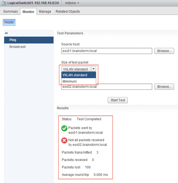
You can verify logical switch operation using the monitor option. This option allows you to send pings between the participating hosts or test a broadcast domain. If you want to test VXLAN functionality choose “VXLAN standard” as the size of a test packet, or you can select “minimum” to run an ordinary network test.
Notice that in this example the VXLAN failed, this has to do with a feature on my switch which doesn’t allow non-standard ICMP packets:
Ping (ICMP) works only up to 1518 bytes and all the other kinds of data traffic should work up to the Jumbo frame limits.
The same network test succeeds when setting the size of the test packet to minimum. VXLAN works perfectly in my environment despite the failing test. Please note that configuring an MTU of 1600 on your physical switch is required for VXLAN to work.
The switch is ready for use now and you can connect virtual machines to the logical switch.
I hope this first article gives some insight on how to configuring a logical switch using VXLAN. In an upcoming article I will demonstrate how to use the vCO NSX plugin to create a logical switch. Happy networking!


3 Comments
Pingback: 2v0-642 Most up-to-date Exam Questions - Free Download Demo
Pingback: Try 2v0-642 Updated Exam Questions and Answers
Pingback: 2v0-642 | 100% passing guarantee on 2v0-642 Exam Questions